Welcome to Arduino!
Circuit 1: Blinking LED
| Circuit 1 Diagram |
Words, Phrases, and Things to Knowvoid setup( )
{ } void loop( ) { } pinMode( _____ , _____ ) digitalWrite( ______ , _______ ) HIGH LOW delay( _____ ) ; INPUT OUTPUT LED |
ChallengePut the wire into a different pin (not pin 13 or 0),
then change the light to blink in a different pattern |
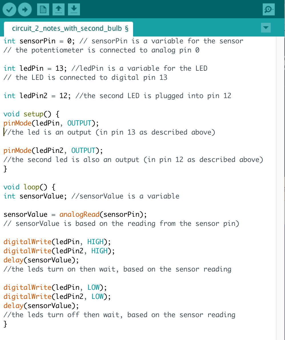
Circuit 2: Potentiometer
| Circuit 2 Diagram |
Words, Phrases, and Things to Knowpotentiometer
int analogRead |
ChallengeMove the LED, potentiometer and necessary wires to different positions on your breadboard
OR Add a second light (to the board and your code) and have to do the same thing as the first LED |
Adding a second bulb:
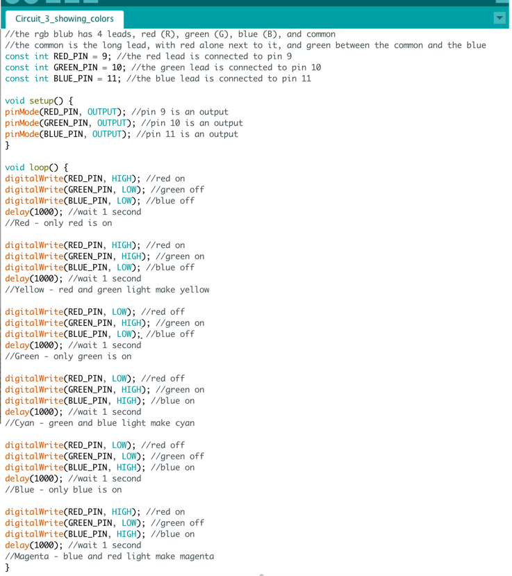
Circuit 3: White LED
|
| ||||
Words, Phrases, and Things to KnowRGB
common const int white light |
ChallengeMake the LED flash between only yellow and magenta.
Note:
|
Showing the primary and secondary colors of light:
Circuit 4: Multiple LEDs
| Circuit 4 Diagram |
Words, Phrases, and Things to Knowindex
array for( ) { } <= ++ random( __ ) |
Understanding this code: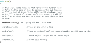
Notice that void loop() does not have much in it. Why is that? Because it is actually running another function, which can simplify your code. If you make oneAfterAnother() a note by adding // in front of it, then take away the // in front of one of the other lines, you can run a different part of the code. Scroll down to look at different functions. Read each function, upload it, and understand how it works and how it is different from the rest.
ChallengeMake lights flash to a song for 30 seconds of the song.
|
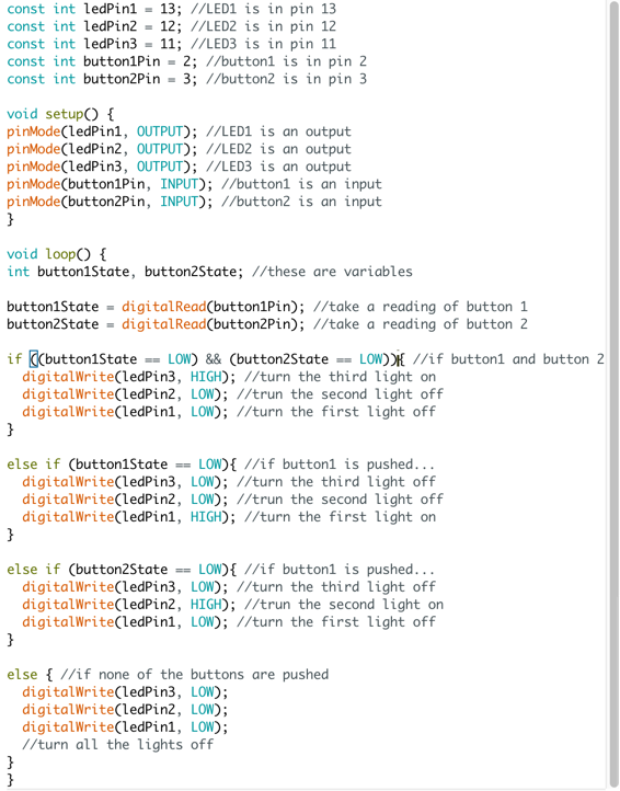
Circuit 5: Buttons
| Circuit 5 Diagram |
Words, Phrases, and Things to KnowdigitalRead( _____________ )
if( ___ ) { } else { } && || &&! |
ChallengeCreate a circuit that lights:
| ||
Coding a circuit with 3 lights and 2 buttons:
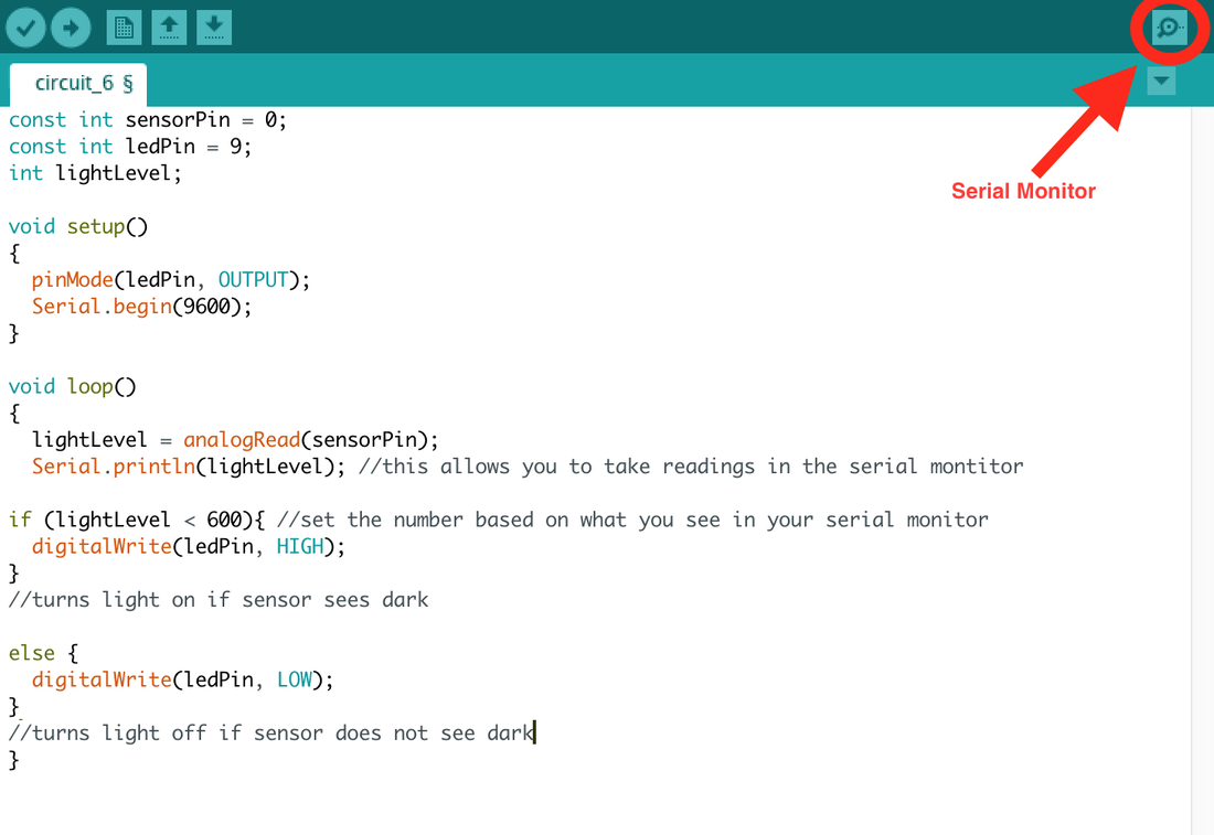
Circuit 6: Photo Resistors
| Circuit 6 Diagram |
Words, Phrases, and Things to Knowmap( ______ , ___ , ___ , ___ , ___ )
constrain( ______ , ___ , ___ ) Serial.println |
ChallengeMake the LED light up when the sensor sees dark
|
Try this!
The code below shows you a simpler way to use the photo resistor. When you do this, you may need to use the serial monitor to determine what the values of light and dark are for your circuit and lighting. Open the serial monitor and watch what happens as you cover and uncover the sensor. Use a number just higher than your lowest numbers in the monitor for the if statement in void loop.
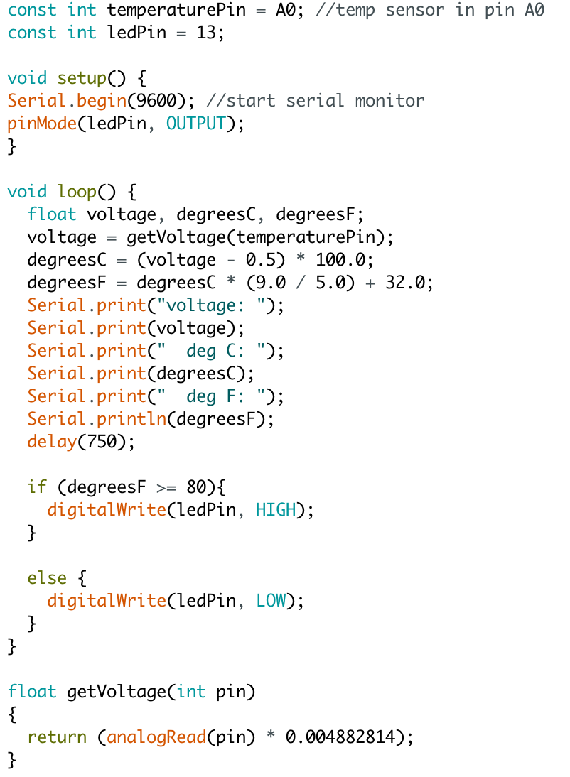
Circuit 7: Temperature Sensor
|
| ||||
Words, Phrases, and Things to Knowfloat
getVoltage( _____ ) Serial.begin( ______ ) Serial.print( _______ ) Serial.println( ________ ) return |
ChallengeTurn on an LED if the temperature is above a certain amount (must be demonstrable, 80 degree F usually works)
|
Circuit 8: Servo
| Circuit 8 Diagram |
Words, Phrases, and Things to Know#include <Servo.h>
Servo ______.attach( ___ ) ______.write( ___ ) [[[pay really close attention to what goes in the parenthesis above!]]] |
ChallengeMake a servo turn forward 90 degrees, turn back 180 degrees, then move forward 20 degrees.
OR For an added challenge, make the servo move to position 90 degrees when one button is pushed and move by 5 degrees every time another button is pushed. |
Circuit 9: Flex Sensor - not in a standard kit
Words, Phrases, and Things to Knowflex sensor
voltage divider |
Challenge |
Circuit 10: Soft Potentiometer - not in a standard kit
Words, Phrases, and Things to Know |
Challenge |
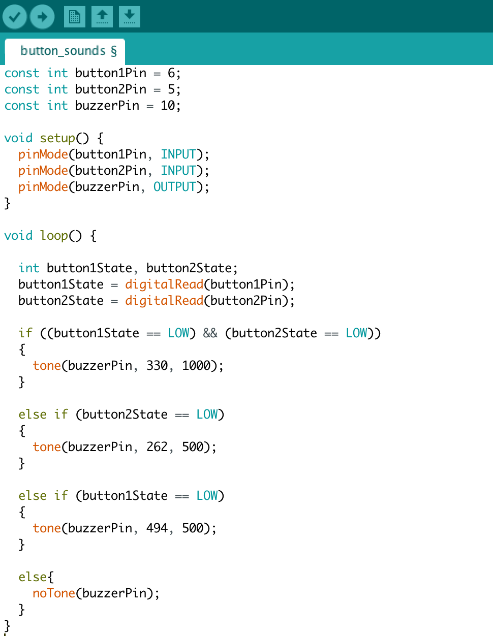
Circuit 11: Piezo Buzzer - not in a standard kit
Words, Phrases, and Things to KnowNotes and frequencies:
|
ChallengeMake two buttons that when pushed each make a different sound
|
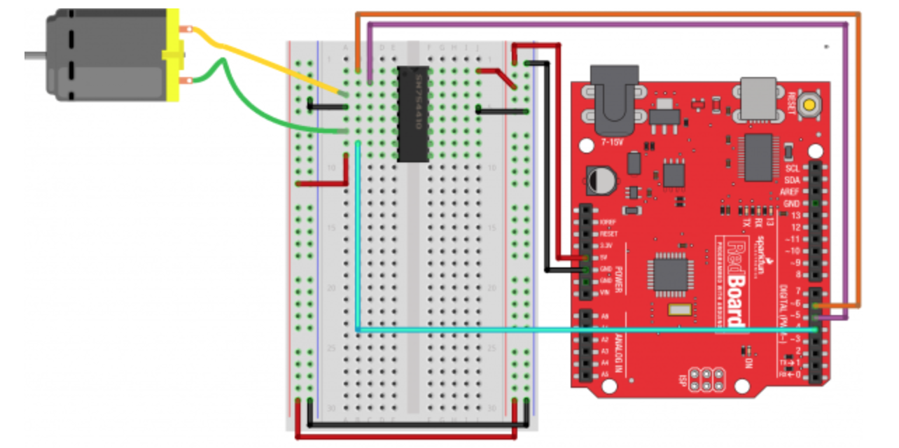
Circuit 12: Spinning Motor
Motor Circuit without Transistor and Diode
/*
SparkFun Tinker Kit
Example sketch 9
SparkFun Motor Driver
Use the SparkFun Motor Driver to control the speed and direction of a motor
This sketch was written by SparkFun Electronics,
with lots of help from the Arduino community.
This code is completely free for any use.
Visit http://learn.sparkfun.com/products/2 for SIK information.
Visit http://www.arduino.cc to learn more about Arduino.
*/
//define the two direction logic pins and the speed / PWM pin
const int DIR_A = 5;
const int DIR_B = 4;
const int PWM = 6;
void setup()
{
//set all pins as output
pinMode(DIR_A, OUTPUT);
pinMode(DIR_B, OUTPUT);
pinMode(PWM, OUTPUT);
}
void loop()
{
//drive forward at full speed by pulling DIR_A High
//and DIR_B low, while writing a full 255 to PWM to
//control speed
digitalWrite(DIR_A, HIGH);
digitalWrite(DIR_B, LOW);
analogWrite(PWM, 255);
//wait 1 second
delay(1000);
//Brake the motor by pulling both direction pins to
//the same state (in this case LOW). PWM doesn't matter
//in a brake situation, but set as 0.
digitalWrite(DIR_A, LOW);
digitalWrite(DIR_B, LOW);
analogWrite(PWM, 0);
//wait 1 second
delay(1000);
//change direction to reverse by flipping the states
//of the direction pins from their forward state
digitalWrite(DIR_A, LOW);
digitalWrite(DIR_B, HIGH);
analogWrite(PWM, 150);
//wait 1 second
delay(1000);
//Brake again
digitalWrite(DIR_A, LOW);
digitalWrite(DIR_B, LOW);
analogWrite(PWM, 0);
//wait 1 second
delay(1000);
}
|
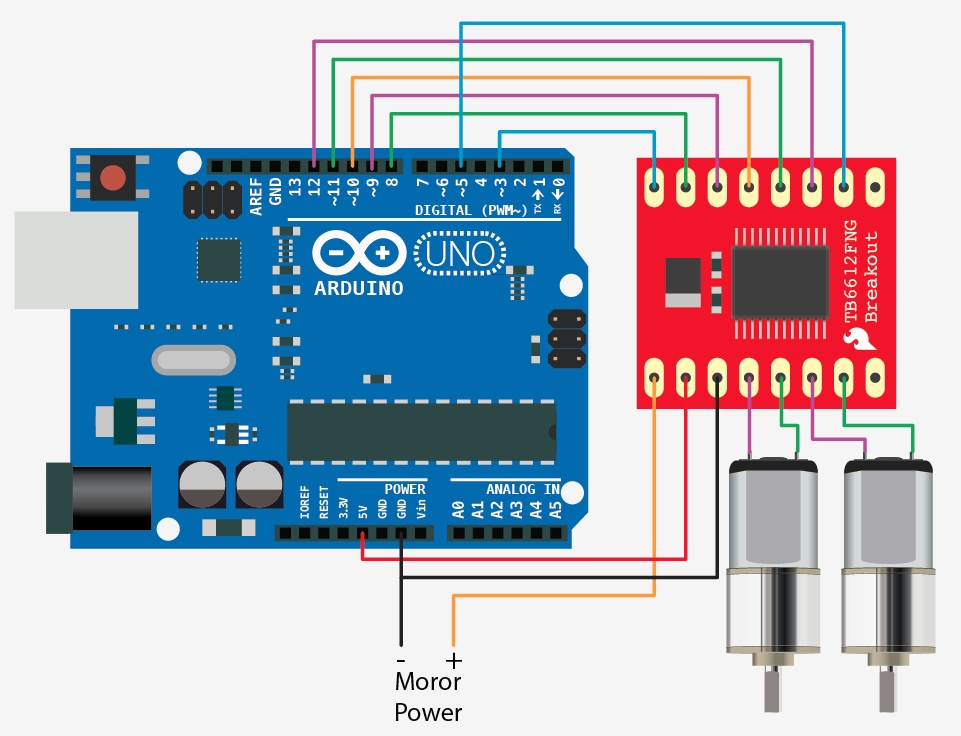
Do not use wire going to motor +
|
//motor A connected between A01 and A02
//motor B connected between B01 and B02
int STBY = 10; //standby
//Motor A
int PWMA = 3; //Speed control
int AIN1 = 9; //Direction
int AIN2 = 8; //Direction
//Motor B
int PWMB = 5; //Speed control
int BIN1 = 11; //Direction
int BIN2 = 12; //Direction
void setup(){
pinMode(STBY, OUTPUT);
pinMode(PWMA, OUTPUT);
pinMode(AIN1, OUTPUT);
pinMode(AIN2, OUTPUT);
pinMode(PWMB, OUTPUT);
pinMode(BIN1, OUTPUT);
pinMode(BIN2, OUTPUT);
}
void loop(){
move(1, 255, 1); //motor 1, full speed, left
move(2, 255, 1); //motor 2, full speed, left
delay(1000); //go for 1 second
stop(); //stop
delay(250); //hold for 250ms until move again
move(1, 128, 0); //motor 1, half speed, right
move(2, 128, 0); //motor 2, half speed, right
delay(1000);
stop();
delay(250);
}
void move(int motor, int speed, int direction){
//Move specific motor at speed and direction
//motor: 0 for B 1 for A
//speed: 0 is off, and 255 is full speed
//direction: 0 clockwise, 1 counter-clockwise
digitalWrite(STBY, HIGH); //disable standby
boolean inPin1 = LOW;
boolean inPin2 = HIGH;
if(direction == 1){
inPin1 = HIGH;
inPin2 = LOW;
}
if(motor == 1){
digitalWrite(AIN1, inPin1);
digitalWrite(AIN2, inPin2);
analogWrite(PWMA, speed);
}else{
digitalWrite(BIN1, inPin1);
digitalWrite(BIN2, inPin2);
analogWrite(PWMB, speed);
}
}
void stop(){
//enable standby
digitalWrite(STBY, LOW);
}
Circuit 13: Relays - not in a standard kit
Circuit 14: Shift Register
Words, Phrases, and Things to KnowIC
|
ChallengeTBD
|
Circuit 15: LCD - not in a standard kit
Words, Phrases, and Things to Know |
Challenge |
Circuit 16: Simon Says - not in a standard kit
Words, Phrases, and Things to Know |
Challenge |
